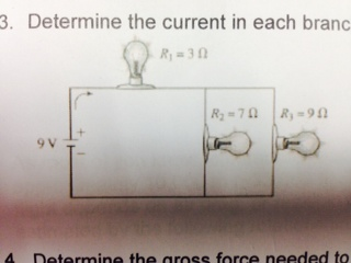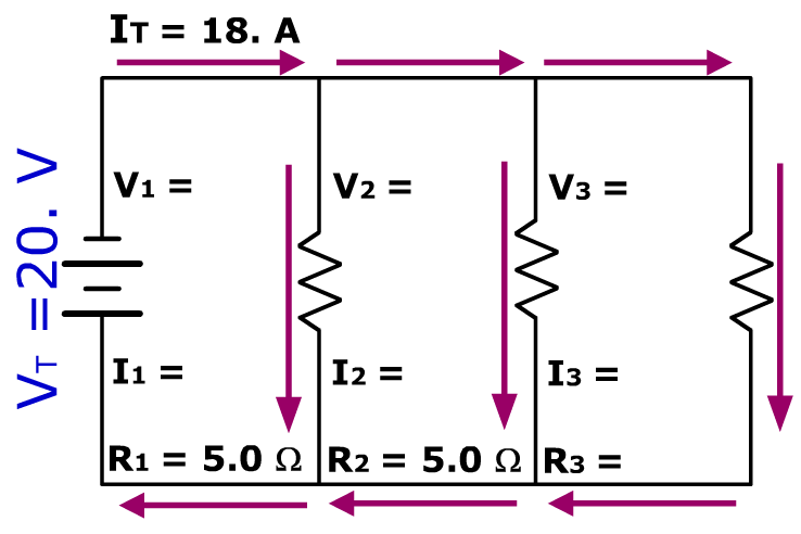

The entire method is illustrated below with two examples.

Once the total resistance of the circuit is determined, the analysis continues using Ohm's law and voltage and resistance values to determine current values at various locations. So in Diagram B, the total resistance of the circuit is 10 Ω.
Parallel circuit definition series#
Now that all resistors are in series, the formula for the total resistance of series resistors can be used to determine the total resistance of this circuit: The formula for series resistance is R tot = R 1 + R 2 + R 3 +. Thus, the two branches can be replaced by a single resistor with a resistance of 2 Ω. Two 4-Ω resistors in parallel is equivalent to a resistance of 2 Ω. Diagram A represents a combination circuit with resistors R 2 and R 3 placed in parallel branches. Then an understanding of the equivalent resistance of a series circuit can be used to determine the total resistance of the circuit. An example of this method was presented in a previous section of Lesson 4.īy applying one's understanding of the equivalent resistance of parallel branches to a combination circuit, the combination circuit can be transformed into a series circuit.

If the two or more resistors found in the parallel branches do not have equal resistance, then the above formula must be used. Where R 1, R 2, and R 3 are the resistance values of the individual resistors that are connected in parallel. This method is consistent with the formula 1 / R eq = 1 / R 1 + 1 / R 2 + 1 / R 3 +. Previously in Lesson 4, the method for determining the equivalent resistance of parallel are equal, then the total or equivalent resistance of those branches is equal to the resistance of one branch divided by the number of branches. Once transformed into a series circuit, the analysis can be conducted in the usual manner. The basic strategy for the analysis of combination circuits involves using the meaning of equivalent resistance for parallel branches to transform the combination circuit into a series circuit.
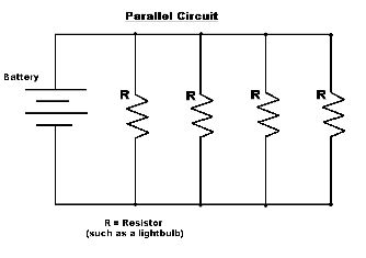
R) allows one to conduct a complete analysis of a combination circuit. Combining the mathematical expressions of the above concepts with the Ohm's law equation (ΔV = I The equivalent or overall resistance of the collection of resistors is given by the equationĮach of the above concepts has a mathematical expression. The sum of the current in each individual branch is equal to the current outside the branches. The voltage drop is the same across each parallel branch. The overall resistance of the collection of resistors is equal to the sum of the individual resistance values,. The sum of the voltage drops across the individual resistors is equal to the voltage rating of the battery. The current is the same in every resistor this current is equal to that in the battery. The main concepts associated with series and parallel circuits are organized in the table below. Since both types of connections are used in combination circuits, the concepts associated with both types of circuits apply to the respective parts of the circuit. When analyzing combination circuits, it is critically important to have a solid understanding of the concepts that pertain to both series circuits and parallel circuits. This is an example of a combination circuit. In this case, light bulbs A and B are connected by parallel connections and light bulbs C and D are connected by series connections. The circuit depicted at the right is an example of the use of both series and parallel connections within the same circuit. A third type of circuit involves the dual use of series and parallel connections in a circuit such circuits are referred to as compound circuits or combination circuits. When all the devices in a circuit are connected by parallel connections, then the circuit is referred to as a parallel circuit. When all the devices in a circuit are connected by series connections, then the circuit is referred to as a series circuit. They can be connected by means of series connections or by means of parallel connections. Previously in Lesson 4, it was mentioned that there are two different ways to connect two or more electrical devices together in a circuit.


 0 kommentar(er)
